Electric Fence Energizer Wiring Guide: How to Connect Fence, Earth and Power
- Share
- Issue Time
- Oct 27,2026
Summary
Wire an energizer EARTH first, FENCE second, power last. This guide covers terminal identification, lead-out cable selection, the wiring sequence for DC, AC, solar and AC/DC units, commissioning readings (6,000-8,000 V at the terminals, 2,000 V minimum at the far end) and the eight wiring mistakes that get reported as energizer faults.
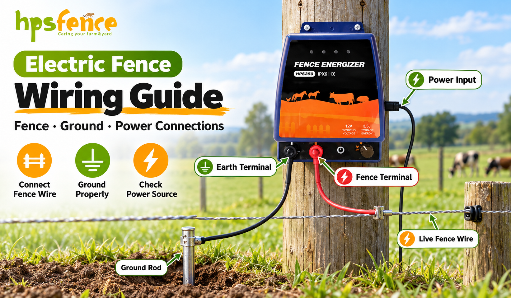
Most energizers returned as faulty arrive with three wires attached in the wrong order, or in the right order and with no earth. The unit is usually fine. What failed is the circuit around it: a lead-out cable that leaks at 8 kV, a battery negative mistaken for the fence earth, or a DC plug pushed into an AC-only input. This guide takes the terminals in order, gives the wiring sequence for each power type, and lists the readings that prove an installation is correct before the customer discovers it is not.
Wire an energizer in this order: EARTH to a dedicated rod system first, FENCE to the live wire second through a lead-out cable rated for the full pulse voltage, power last. A 3.5 J unit needs four 20 mm × 1 m earth rods spaced at least 3 m apart, and the fence should read 6,000–8,000 V at the terminals with no less than 2,000 V at the far end for cattle or 3,000 V for wooled sheep. Connect power only after both high-voltage connections have been checked.
Quick facts
- Three connections decide the installation: FENCE, EARTH and power. The first two carry the pulse; the third must never touch either of them.
- Open-circuit terminal voltage on a healthy installation sits at 6,000–8,000 V, and must not fall below 2,000 V at the far end for cattle, 3,000 V for wooled sheep.
- Earth side: one 20 mm × 1 m galvanised rod per joule of output, at least 3 m apart along the fence line (KZN Agriculture & Rural Development).
- IEC 60335-2-76 caps fence output at 5 J per pulse, 10 ms duration and 1 Hz repetition — which is why a dedicated lead-out, not fence wire, carries the connection.
What an electric fence energizer wiring system is
An energizer is a capacitor bank and a transformer in a sealed box. It stores energy from the supply, dumps it onto the fence as a short pulse, waits about a second, and repeats. Everything outside the box — the lead-out, the fence conductor, the animal, the soil, the rods — is the circuit that pulse has to complete.
That is why wiring is not a detail. The box can deliver a textbook pulse and the fence still fail, because the pulse never returns. A 2 J unit wired properly will hold cattle where a 12 J unit with one rod and a leaking lead-out will not.
Read the circuit as a loop, not as a wire that ends in the paddock: energizer FENCE terminal → lead-out cable → live fence wire → animal contact → soil → earth rods → energizer EARTH terminal.
| Element | Job in the circuit | What fails when it is wrong |
|---|---|---|
| Lead-out cable | Carries the pulse from the terminal to the fence without leaking it | Voltage disappears at the terminal box; the fence reads low from the first post |
| Live fence conductor | Delivers the pulse along the fence line | Joints and corrosion add resistance; the far end halves |
| Insulators | Stop the live wire discharging into posts and soil | A constant load the energizer cannot report |
| Earth rods | Collect the return current from the soil | Weak shock even when the voltage looks reasonable |
| Power input | Feeds energy into the capacitor bank | Unit runs flat, resets, or is damaged by wrong polarity |
Electric fence energizer terminals: FENCE, EARTH and power input
Terminal layouts differ between models and colours are not a standard. Read the moulded marking, not the wire your predecessor used. On HPS FENCE units the high-voltage pair sits apart from the low-voltage input block; on other brands the two can be adjacent.
| Terminal | Marking | Connects to | The mistake we see |
|---|---|---|---|
| Fence output | FENCE / + / red | Live fence wire, via lead-out cable | Connected to the earth rod, which shorts the output |
| Earth | EARTH / GROUND / − | Dedicated rod system, separate from building earth | Left unconnected because “the post is steel” |
| DC positive | 12 V + / battery + | Battery positive through the supplied lead | Reversed polarity, which can destroy the board |
| DC negative | 12 V − / battery − | Battery negative | Treated as the fence earth — it is not |
| AC input | AC 110–240 V | Approved adapter or fixed supply | Raw mains wired to the fence output |
| Solar input | PANEL / SOLAR | Matched panel or controller, per manual | Panel wired straight to the battery |
If a marking is missing or unreadable, stop. A wrong guess at the high-voltage pair costs a board; a wrong guess at the power pair costs a fire.
Step 1 — mount the energizer where its IP rating holds
IPX6 means water projected at the enclosure from any direction does not enter. It does not mean the unit can sit in a puddle, under a downpipe, or inside a sealed cabinet that traps heat. Mounting decides how long the wiring lasts, because a flooded terminal block corrodes from the inside out.
- Above flood level and clear of drip lines — 300 mm of clearance under the unit, and nothing overhead that pours onto the lid.
- Out of direct afternoon sun where the housing is dark; internal temperature shortens capacitor life.
- Ventilated, not sealed. A closed plastic box in summer becomes an oven and condenses at night.
- Reachable without tools, because a unit that is hard to inspect is a unit that never gets inspected.
- Within 1–2 m of the earth rods so the earth conductor stays short and does not run beside the live lead.
Step 2 — earth the energizer before the fence
Earth first, because the fence is meaningless until the return path exists, and because it is the step that gets skipped at five in the afternoon before rain. The short version: one 20 mm × 1 m galvanised rod per joule, driven along the fence line at least 3 m apart, clamped with galvanised fittings, and connected to EARTH with a dedicated conductor.
Rod count, spacing, soil treatment and the remote-rod test are covered in full in our electric fence grounding guide. What belongs here is the wiring rule installers break: the fence earth is a separate circuit. Do not bond it to the building earth, the water pipe, or the mains earth inside an AC/DC unit, even when that unit is running from mains.
Step 3 — connect the FENCE terminal to the live wire
The lead-out is the only part of the installation carrying the full pulse voltage, and it is the part most often replaced with whatever was in the van. Ordinary flex, twin-and-earth, or a spare length of fence wire will leak at 8–10 kV, and the leak shows up as a fence that reads low from the first post while the energizer tests perfectly on the bench.
- Use dedicated lead-out cable rated for the pulse voltage — thick insulation, single conductor, not two thin cores.
- Keep the run as short as the layout allows, and take it through conduit or a buried sleeve where vehicles or stock cross.
- Do not run the lead-out parallel to the earth conductor for more than a couple of metres; induced leakage costs voltage you cannot see.
- Terminate with a proper connector at the fence, not wire twisted around the conductor and taped.
- Check the first insulator. A live wire resting on a steel post is a permanent short, and the energizer reads it as load, not as a fault.
DC and AC energizer wiring: battery leads and mains adapters
These two types look different at the supply end and identical at the fence end. The fence circuit is always FENCE to the live wire and EARTH to the rods; only the two power terminals change.
| Type | Supply | Wiring sequence | Typical models |
|---|---|---|---|
| DC | 12 V battery | Battery + → DC +, battery − → DC −, then FENCE and EARTH | HPS050, HPS100, HPS200, HPS350 |
| AC | 110–240 V adapter or fixed supply | Approved adapter → AC input, then FENCE and EARTH | HPS480, HPS800 |
| AC/DC | Mains or 12 V battery | One supply at a time unless the manual states otherwise | HPSA200-AC/DC, HPS350 |
| Solar | Panel, controller and 12 V battery | Panel → controller → battery → energizer, then FENCE and EARTH | HPSS350, HPSS600, HPS100S |
On DC units, check polarity with a meter before the lead touches the terminal. Reverse polarity on a 12 V input can destroy the switching board in a second, and it is not a warranty case because the manual states the polarity. Use the supplied or approved leads rather than croc clips on a battery that also feeds a yard light.
On AC units the mains side is fixed wiring and belongs to a qualified electrician where local rules require it. What the installer must check is duller and more important: that the adapter output matches the model's rated input, and that nobody has cut the plug off and wired it into a farm circuit that also carries a welder.
Solar and AC/DC energizer wiring: panel, controller, dual supply
Integrated solar energizers keep the controller and battery inside the housing; the installer connects a panel to the marked input, or nothing at all when the panel is built in. Separate-component systems are the ones wired incorrectly, because there are four devices in a row and every one of them can be connected to the wrong neighbour.
- Panel to controller, controller to battery, battery to energizer. A panel wired straight to a battery has no regulation and will cook it in one summer.
- Match panel voltage to the controller, then check that the controller output matches the energizer's DC input.
- Keep the panel clear of the fence's own shadow — a post that shades it for two hours a day is a battery that never reaches full charge.
- On AC/DC units, use one supply at a time unless the manual explicitly supports simultaneous connection or automatic changeover.
The full mounting and commissioning sequence for each of these three power types, with the model videos, is in our energizer installation guide.
How to test an electric fence after wiring
Test in this order and each reading tells you where the fault is. Skip the order and every number becomes ambiguous.
| Test point | Target reading | If it is low |
|---|---|---|
| Energizer terminals, open circuit | 6,000–8,000 V | Power supply or internal fault — check the input first |
| Lead-out at the fence start | Within 5–10% of the terminal reading | Lead-out leaking, or a bad termination |
| Mid-fence | No more than about 20% below the start | Insulator faults, vegetation contact, corroded joints |
| Far end | ≥2,000 V cattle · ≥3,000 V wooled sheep | Return path, joints or fence loading — not the energizer |
Use a purpose-built fence tester. A household multimeter rated for 1,000 V is not a fence instrument, and the pulse will damage it.
The load test matters more than the open-circuit number. An energizer reading 9,000 V into air proves the capacitor works; it proves nothing about the fence. Read the far end with the fence connected and wet, because that is the condition the stock will meet.
Electric fence energizer wiring mistakes that read as faults
| Wiring mistake | What the customer reports | What is actually wrong |
|---|---|---|
| FENCE terminal wired to the earth rod | No voltage, or a few hundred volts | Output shorted to the return path |
| One earth rod on a 4.8 J unit | Respected for a week, then ignored | Return path cannot carry the pulse |
| Ordinary flex used as lead-out | Strong at the box, weak at the first post | Insulation breaking down at pulse voltage |
| Battery negative used as fence earth | Erratic readings, occasional dead unit | Two different circuits treated as one |
| Reversed battery polarity | Unit dead or fuse blown on first connection | Switching board damaged |
| Live wire touching a steel post | Voltage falls through the day | Permanent short the energizer cannot report |
| Lead-out run beside the earth conductor | Far end weak, open circuit looks fine | Induced leakage between the two conductors |
| Wrong adapter on an AC unit | Unit resets, buzzes or overheats | Input voltage or current outside specification |
No voltage after wiring: the four-step check
A dead fence is a sequence problem, not a mystery. Work back from the supply and stop at the first reading that fails.
- Power. Battery voltage under load, adapter output, panel charge. A 12 V battery at 11.4 V will run the unit but not hold a fence.
- Terminals. Confirm the tester reads a pulse at FENCE, and that EARTH is genuinely connected to the rods rather than to the fence's steelwork.
- Lead-out and fence. Disconnect the lead-out at the fence and read the terminal again. If voltage returns, the fault is downstream; if not, it is in the box or the supply.
- Earth. Read between the last rod and a temporary rod 20–30 m away. A significant reading means the soil is not carrying the return current.
If the first three pass and the fence still underperforms, the fault is almost always the earth or the joints — the two things nobody photographs. Our energizer troubleshooting guide takes the diagnosis further into storm damage and internal faults.
Delivered output, not label input. The gap between the two is why a 6 J solar unit is compared with a 3.6 J mains unit rather than with a 6 J one.
HPS FENCE as an electric fence energizer manufacturer
HPS FENCE is the brand of Hangzhou Opus Fence Supplies Co., Ltd, building energizers in Hangzhou since 2013 with category experience back to 2002. Output spans 0.25 J to 12 J across mains, battery, solar and AC/DC formats, sealed to IPX6, with CE, RoHS, TÜV and SGS documentation supplied for import. Units ship to distributors in Australia, New Zealand, Europe, the United States, Canada, South America, Korea and Japan. Batch records, test reports and the terminal drawings behind this guide all come from the same factory that builds the units.
Real output test method published, not just a label value.
Read the test methodContinuous run with output, energy and temperature monitored.
See the production processPackaging verified for container and parcel transit.
See the drop testVerified per production batch, not on a single prototype.
View certificationsEvery unit checked before packing, with batch traceability.
Inspection stepsOutput and safety data filed by model and batch, supplied with the order.
Request a batch recordPrivate label and OEM for energizer ranges
Private label covers the housing label, retail box, manual, model naming, colour and output specification. For wiring, two items get customised most often: the plug and lead set, so the unit arrives ready for the destination market, and the manual's wiring diagram, printed in the buyer's language with the terminal layout of that exact model.
Branding and packaging
- Logo on housing, retail box and manual
- Model naming and colour to suit your catalogue
- Packaging engineered for e-commerce and container transit
Technical and documentation
- Output voltage and joule specification per market
- Multilingual manuals, including installation guides
- Full ODM development with scheduling and sample approval
Wholesale terms for energizer buyers
Energizers and the power input they need

2 J dual source
2 J delivered · 9 kV peak · AC or 12 V
Mains where available, battery where not — one unit for both jobs.
View product details
3.5 J AC/DC
3.5 J · 55 miles clean fence · 250 acres
The volume model for mixed dealer catalogues.
View product details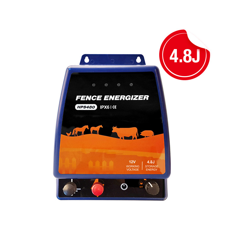
4.8 J AC
4.8 J · AC 110 V · extra power reserve
Permanent mains installations with heavy vegetation.
View product details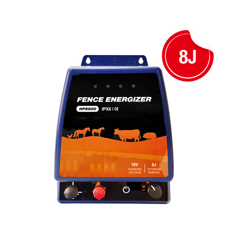
8 J high power
8 J input · 4.8 J delivered · 13 kV · 80 km
Reserves, wildlife boundaries and long runs.
View product details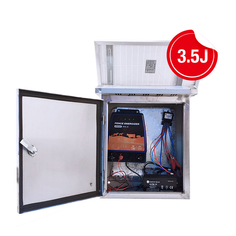
Solar 3.5 J
3.5 J input · 2.1 J delivered · 30-mile range
Remote paddocks with no mains within reach.
View product details
Solar 6 J
6 J input · 3.6 J delivered · 60-mile range
Long remote cattle runs and rotational grazing.
View product detailsElectric fence energizer wiring FAQ
Which terminal connects to the fence wire?
The terminal marked FENCE, Fence Output, + or red. It connects to the live conductor through a lead-out cable rated for the pulse voltage. Confirm the marking against the manual for that model — colours are not standardised between brands.
Can I connect the fence wire directly to a 12 V battery?
No. The battery only powers the energizer; the energizer generates the high-voltage pulse. A battery wired to the fence puts 12 V DC on the wire, which carries no pulse and will not stop stock.
Can I use ordinary household cable as the lead-out?
Not safely. Standard flex and twin-and-earth are insulated for mains voltage, not for a 6,000–10,000 V pulse, and they break down. Use dedicated electric fence lead-out cable, kept as short as the layout allows.
What is the MOQ for wholesale energizers with leads and earth kits?
One unit on energizers, testers and coop doors; 100 units on other categories. Lead-out cable, earth rods, clamps and testers can be mixed into the same shipment, so a dealer can quote the whole circuit in one order.
Can a distributor order energizers with their own plug and manual language?
Yes. Private label covers the plug and lead set, housing label, retail box, model naming and manual language, with the wiring diagram redrawn for that model's terminal layout. Minimum order and schedule are confirmed per project.
Sources
- IEC 60335-2-76:2002+A1:2006 / BS EN IEC 60335-2-76:2021 — output energy ≤5 J, pulse duration ≤10 ms, repetition rate ≤1 Hz.
- KZN Department of Agriculture & Rural Development — Electric Fencing in Agriculture: 20 mm × 1 m earth rod specification, spacing, and minimum far-end voltage by stock class.
- HPS FENCE product specifications — output energy, power source and terminal layout across the 0.25–12 J range.
- HPS FENCE — How to Test Real Output: measured efficiency and the stored-versus-delivered gap.
HPS FENCE · MANUFACTURER & WHOLESALE SUPPLIER
Your Trusted Partner for Electric Fencing & Farm Solutions
From electric fence energizers and fencing accessories to poultry farming equipment, HPS FENCE supports global distributors, wholesalers, importers, and brands with reliable products, flexible OEM/ODM customization, and long-term supply solutions.